Heating Elements and Radiant Systems in Concrete Floors
By Housey · Last reviewed 24th of May 2026
Heating Elements and Radiant Systems in Concrete Floors
Underfloor heating in a concrete floor is a common design decision when extending a ground floor, laying a new slab, or planning an energy upgrade alongside a heat pump installation. Getting the specification right — particularly the insulation depth, screed type, and flow temperature — determines whether the system performs efficiently over the long term. Mistakes are difficult and expensive to correct once the floor is poured.
Key points
- Wet (hydronic) underfloor heating in concrete typically runs at flow temperatures of 35–50°C, compared with 60–80°C for conventional radiators, making it the preferred emitter for heat pumps under MCS design guidance (MCS HDD001).
- The minimum recommended screed depth over UFH pipework is 65 mm for standard sand:cement screeds and 30–50 mm for liquid anhydrite screeds — always check the specific manufacturer's specification.
- Omitting sub-floor insulation is the most common energy-performance error in concrete UFH installations; heat is lost downward into the ground rather than upward into the living space.
- Electric UFH mat systems draw approximately 100–160 W/m² and are best suited to supplementary single-room heating — such as bathroom tiling — rather than whole-house primary systems.
- Building Regulations Part L requires adequate sub-floor insulation for ground floors; check the current version of Approved Document L for the U-value target applicable to your project type.
How does radiant floor heating in concrete work?
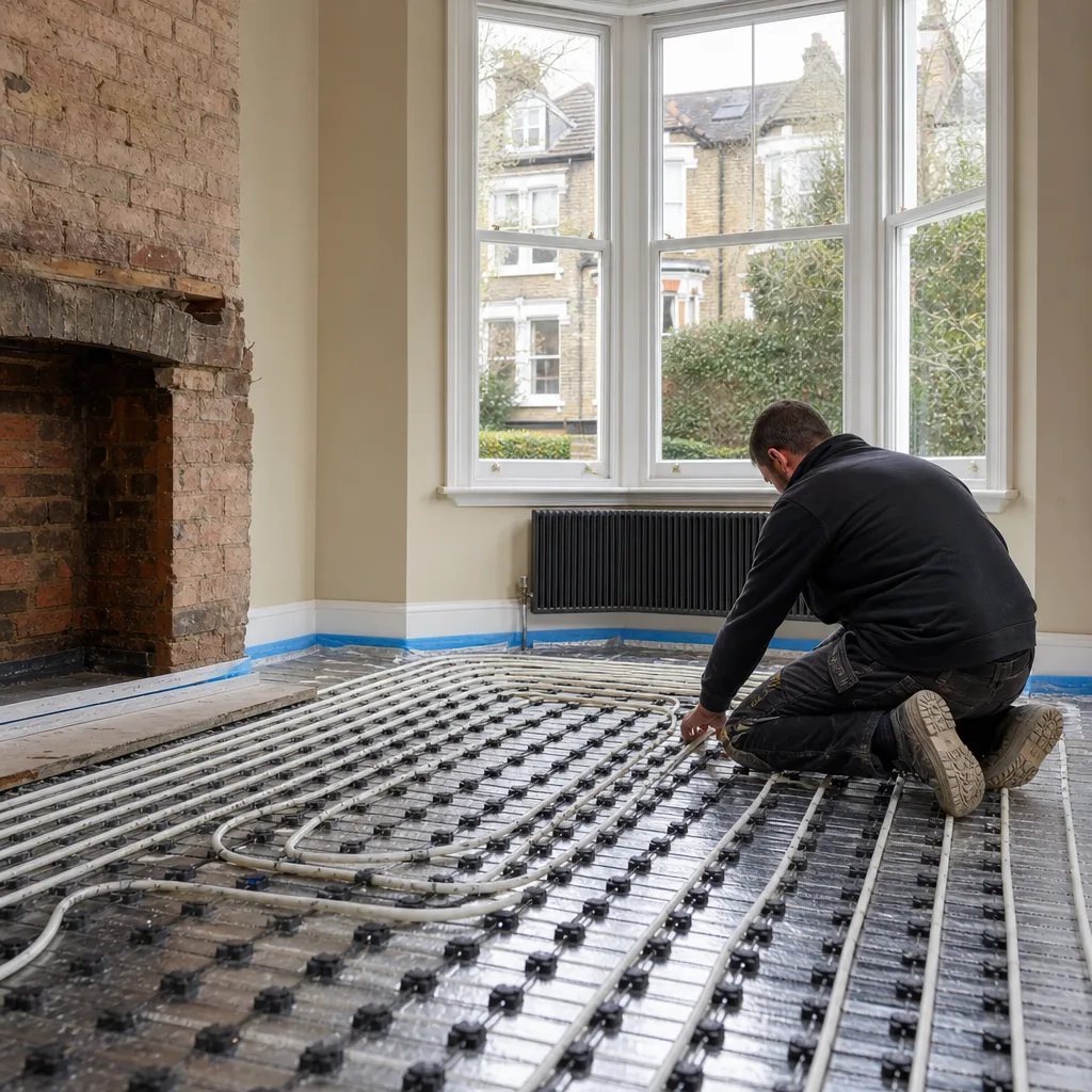
A wet (hydronic) UFH system circulates warm water through flexible polyethylene pipes — typically PE-RT or PEX-a — embedded in a concrete slab or screed. Heat radiates upward from the floor surface, warming occupants and room surfaces through radiant transfer rather than primarily through convection. This mechanism is generally considered more comfortable than warm-air or radiator systems at equivalent air temperatures.
The concrete or screed acts as a thermal store, absorbing heat during periods of generation and releasing it steadily over several hours. This slow-response characteristic makes concrete-embedded systems effective when paired with time-of-use electricity tariffs or heat pumps running on overnight off-peak rates.
Wet systems versus electric mat systems
Feature | Wet (hydronic) system | Electric mat or cable system |
|---|---|---|
Installation | Pipes embedded in screed or slab | Mat or cable laid below tile adhesive or in screed |
Running cost | Lower long-term if on a heat pump | Higher — direct electricity use |
Best paired with | Heat pump, gas or oil boiler | Supplementary room heating, bathrooms |
Screed depth needed | 65–80 mm sand:cement; 35–50 mm anhydrite | 15–25 mm in tile adhesive; 50–65 mm in screed |
Response time | 1–4 hours (concrete thermal mass) | 20–60 minutes (shallow systems) |
Suitable for retrofit | Possible but requires floor-level rise | Easier — thinner profile |
Whole-house primary heating | Yes, if designed correctly | Only if installed capacity is sufficient |
Installing wet UFH in a new concrete slab
A new ground floor slab offers the best opportunity for a correctly designed wet UFH system. The typical build-up from ground level upward is:
- Compacted hardcore and blinding layer
- Radon barrier or damp-proof membrane, if required by site conditions or ground investigation
- Sub-floor rigid insulation — typically 100–150 mm PIR or EPS to achieve Part L targets
- UFH pipework clipped to mesh or proprietary panel insulation
- Structural slab or screed topping — 65–80 mm sand:cement, or 35–50 mm liquid anhydrite
The insulation layer is critical. Without it, a significant proportion of the heat output is lost downward into the ground, reducing both system efficiency and occupant comfort.
Retrofitting UFH into an existing concrete floor
Adding a wet UFH system to an existing solid concrete floor almost always requires raising the floor level. Common approaches include:
- Overlay screed: a new insulation layer (typically 50–75 mm PIR) plus a new screed, raising the floor by approximately 100–130 mm. This affects door thresholds, skirting heights, and connections to adjoining floor levels throughout the ground floor.
- Shallow overlay systems: proprietary aluminium-spread plate systems with thin-profile UFH pipe designed for a 25–40 mm total overlay, reducing the floor-level rise at some trade-off in thermal output.
- Electric mat under tiles: no meaningful floor raise beyond the tile adhesive depth; a practical option for supplementary heating in bathrooms and kitchens.
Before committing to a retrofit, check whether a continuous damp-proof membrane exists beneath the existing slab, what insulation thickness is practical within the available floor-level tolerance, and whether door frames and adjoining rooms can accommodate the required rise.
Flow temperature and heat pump compatibility
One of the principal advantages of concrete-embedded UFH is that it operates efficiently at low flow temperatures — typically 35–45°C — which aligns with the efficient operating range of air source and ground source heat pumps. Conventional radiators in the same building typically need 55°C or higher to output sufficient heat, which reduces heat pump efficiency (measured as coefficient of performance, COP).
MCS HDD001, the heat pump design standard used by MCS-accredited installers, requires that emitter systems — including UFH — are designed to deliver the required heat output at the specified design flow temperature. This calculation should be carried out by a qualified heat pump installer or mechanical building services engineer.
Homeowner checklist before commissioning UFH in a concrete floor
Important limitations
This article provides general information about underfloor heating systems in concrete floors and is not a substitute for a site-specific design or professional assessment. System performance depends on building fabric, heat source type, floor finish, ground conditions, and installation quality. Standards and minimum requirements differ between England, Scotland, Wales, and Northern Ireland. Always consult a qualified heating engineer or retrofit assessor for your specific property and heat source.
When this becomes urgent
Seek professional advice promptly if:
- You notice damp, condensation, or mould after UFH installation or commissioning — this may indicate a DPM failure or moisture trapped within the screed
- Pipework has been damaged during subsequent drilling or floor-laying activities
- The system is underperforming noticeably after commissioning — insufficient insulation or poor zone balancing are common causes requiring diagnosis by a qualified engineer
What to ask a qualified professional
Before instructing a UFH installer or heat pump engineer, ask:
- What is the calculated design flow temperature, and how was it determined?
- What sub-floor insulation thickness are you specifying, and what U-value does it achieve?
- For heat pump systems: are you MCS-accredited, and which standard governs your emitter design?
- How will you pressure-test the pipework before screeding, and what certificate will you provide?
- What screed curing programme do you recommend, and what occupation constraints does it impose?
- How will zones and controls be configured, and what weather-compensation strategy do you recommend for the heat source?
When to get professional help
A qualified heating engineer or mechanical building services consultant should always be involved for a primary UFH system, and particularly if:
- You are pairing UFH with a heat pump and need a whole-system efficiency calculation
- The existing concrete floor has no DPM or shows signs of rising damp
- Structural changes to the floor slab are planned alongside the UFH installation
- There is any doubt about whether the existing heat source can deliver adequate output at low flow temperatures
How Housey can help
Housey connects you with accredited professionals offering retrofit assessments and energy-efficiency consultants who can evaluate your floor build-up, heat source compatibility, and insulation specification before any pipework is laid.
Frequently asked questions
Can I add underfloor heating to an existing solid concrete floor without raising the floor level?
In most cases, some floor-level rise is unavoidable if you want adequate insulation beneath a wet UFH system. Shallow overlay systems using aluminium-spread plates and thin-profile pipe can reduce the rise to 30–40 mm, but there is usually a trade-off with thermal output. Electric mat systems installed directly under tiles add minimal height and are practical for supplementary heating in single rooms.
What floor finishes work best with concrete-embedded underfloor heating?
Stone, ceramic, and porcelain tiles conduct heat readily and perform best. Engineered timber boards up to approximately 18 mm, with a combined thermal resistance below 0.15 m²K/W, are generally suitable if specified for use over UFH — check the manufacturer's guidance. Solid timber boards and thick carpet are less effective and should be discussed with your installer before specifying.
Does underfloor heating in concrete work well with an air source heat pump?
Yes — this is one of the most effective combinations in UK low-energy homes. Concrete UFH's low flow temperature requirement (35–45°C) aligns well with the efficient operating range of air source heat pumps. A properly designed, well-insulated system installed by an MCS-accredited engineer can significantly reduce running costs compared with a conventional radiator circuit.
How long does a wet UFH screed take to cure before flooring can be laid?
A standard sand:cement screed at 70 mm typically takes 6–8 weeks to cure naturally. Liquid anhydrite screeds (30–50 mm) may be walkable within 24–48 hours but still need 4–6 weeks before floor finishes are applied. UFH should be commissioned gradually — starting at 25°C and increasing by 5°C per day — to avoid thermal shock cracking. Ask your installer for a written commissioning programme.
Sources and further reading
- Approved Document L — Conservation of Fuel and Power — GOV.UK
- MCS HDD001 — Heat pump design standard — MCS
- Energy Saving Trust — Heat pumps — Energy Saving Trust
- CIBSE Guide F — Energy Efficiency in Buildings — CIBSE
Useful next reads
 Energy & Retrofit
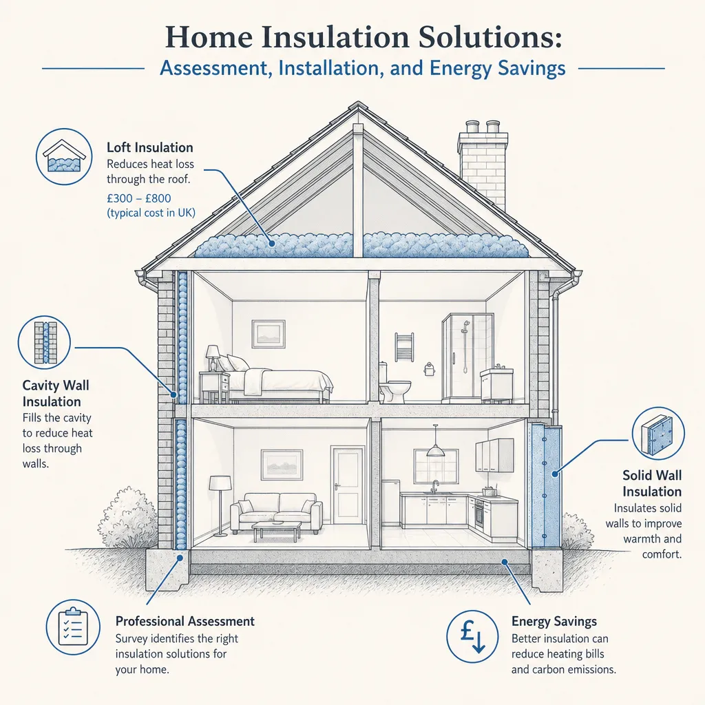
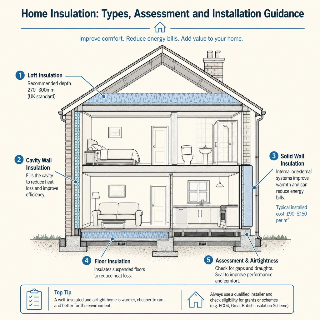
Home Insulation Solutions: Assessment, Installation, and Energy Savings
Home insulation in the UK covers loft, cavity wall, solid wall, and floor insulation.
 Energy & Retrofit
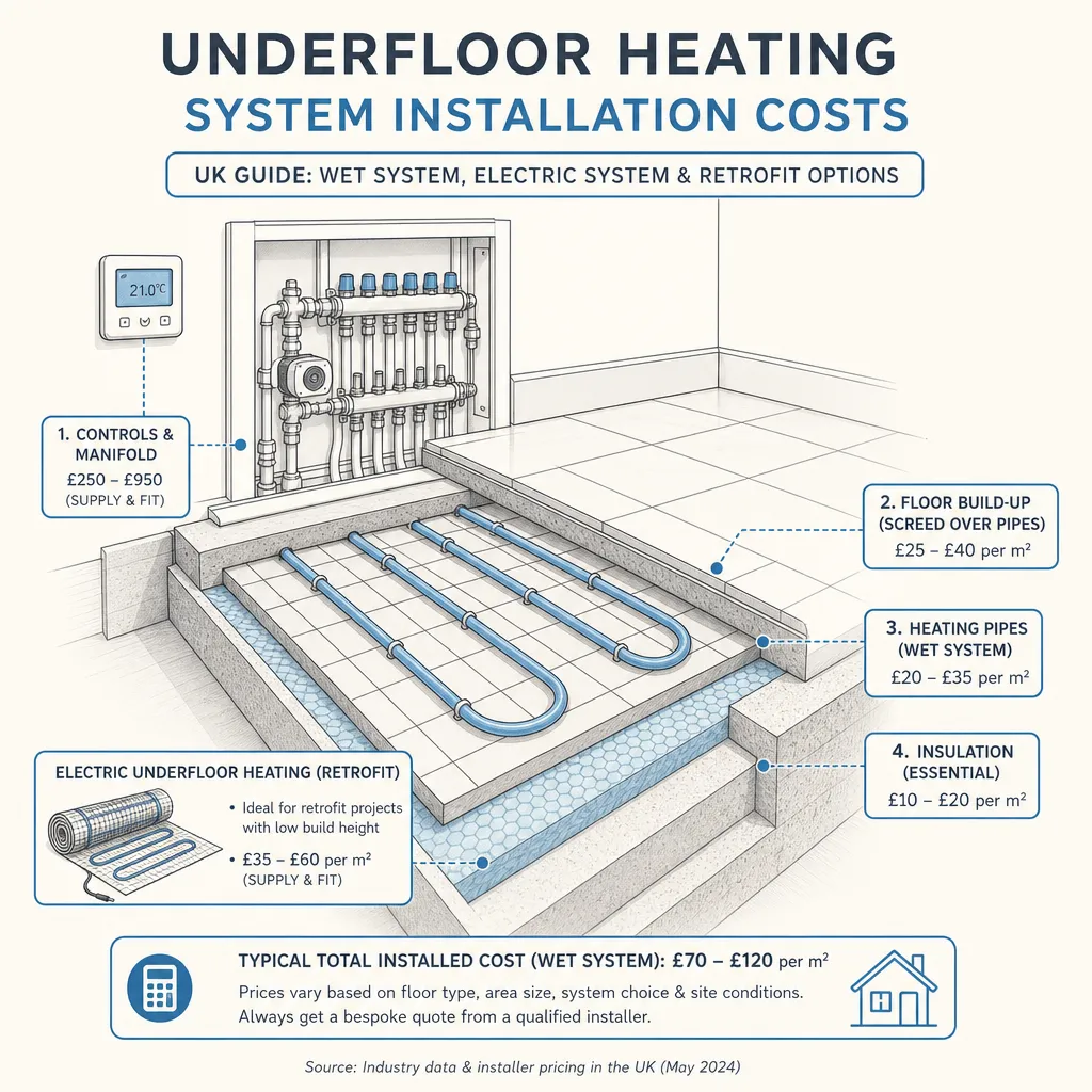
Underfloor Heating System Installation Costs
Underfloor heating installation in the UK typically costs £20–£50 per m² for electric mat or foil systems and £50–£150 per m² for wet (hydronic) systems, including labour.
 Energy & Retrofit
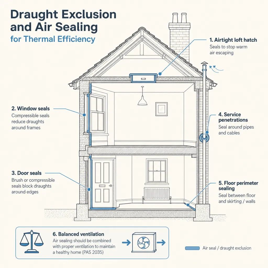
Draught Exclusion and Air Sealing for Thermal Efficiency
Draught proofing and air sealing can cut uncontrolled heat loss by 15–25% in a typical UK home, but sealing a building too tightly without reviewing ventilation risks condensation, mould, and poor air quality.
 Energy & Retrofit
Underfloor Heating Systems: Advantages and Disadvantages
Wet underfloor heating distributes warmth evenly at lower surface temperatures than radiators, making it well-suited to heat pumps.
 Energy & Retrofit
Home Insulation: Types, Assessment and Installation Guidance
Home insulation reduces heat loss through walls, roofs, and floors.